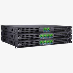
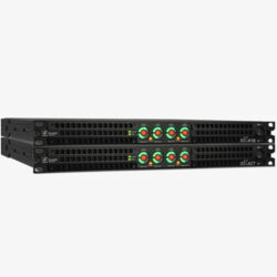
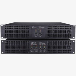
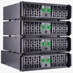
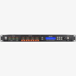
SDX Series DSP Power Amplifiers

SDX-Series User Interface


The SDX series is the natural progression from the popular 1U SX series using D-technology. By integrating DSP components that were developed and manufactured in Germany, impressive performance specifications have been achieved. Like the DSM-428 and 428-FIR DSP processors, SDX power amplifiers can be managed and programmed via the DSM Network Client. SDX power amplifiers can be controlled individually or in groups using DSM software. The output power has also been significantly increased. The SDX-427 now delivers 4 x 3,500 watts into 8 ohms and the SDX-418 delivers 4 x 2,000 watts into 8 ohms.
Übersicht SDX-Endstufen
| Model | SDX-418 | SDX-427 |
| System Type | 4-channel DSP Class D amplifier |
4-channel DSP Class D amplifier |
| Output power | 4 x 4950W @ 2Ohm 4 x 3250W @ 4Ohm 4 x 2000W @ 8Ohm |
4 x 8600W @ 2Ohm 4 x 5670W @ 4Ohm 4 x 3500W @ 8Ohm |
| Dimensions | 483W x 486D x 44H | 483W x 486D x 44H |
| Net Weight | 11,5 kg | 11,5 kg |
Technical Specifications for SDX Power Amplifiers
| Model | SDX-418 | SDX-427 |
| GS1 (EAN) CODE | 4260318513272 | 4260318513289 |
| System Type | 4-channel DSP Class D amplifier |
4-channel DSP Class D amplifier |
| Output power | 4 x 4950W @ 2Ohm 4 x 3250W @ 4Ohm 4 x 2000W @ 8Ohm |
4 x 8600W @ 2Ohm 4 x 5670W @ 4Ohm 4 x 3500W @ 8Ohm |
| Output Power (Bridge Mode) | 2 x 8400W @ 4Ohm 2 x 6600W @ 8Ohm 2 x 4000W @16Ohm |
2 x 14700W @ 4Ohm 2 x 11550W @ 8Ohm 2 x 7000W @16Ohm |
| THD+N @ 8Ω 1kHz,1dB | ≤0.05% | ≤0.05% |
| Slew Rate | >30v/μs | >30v/μs |
| Frequency Response @1Watt, 8Ohm |
10Hz - 20kHz ±0.35dB |
10Hz - 20kHz ±0.35dB |
| Damping Factor (@100Hz) |
>3000 | >3000 |
| Signal to Noise Ratio 20Hz -20 kHz |
>99dB | >99dB |
| Channel Separation Crosstalk@1kHz |
>70dB | >70dB |
| Voltage Gain | 42dB (1,54V:127V) | 45,5dB (1,54V:168V) |
| Input Sensitivity | 1,54 Vrms 6dBu max. 20 dBu |
1,54 Vrms 6dBu max. 20 dBu |
| Input Impedance | 20k Ohm Balanced 10k Ohm Unbalanced |
20k Ohm Balanced 10k Ohm Unbalanced |
| Frontpanel Controls | Power switch, mute button | Power switch, mute button |
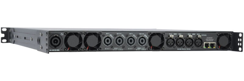
| Backpanel Controls | Sensitivity switch, Mode switch |
Sensitivity switch, Mode switch |
| LED Indicators | Signal VU meter Protect display, Parallel mode display |
Signal VU meter Protect display, Parallel mode display |
| Input Connectors | XLR electronically balanced Pin 1 GND Pin 2+ Pin 3- |
XLR electronically balanced Pin 1 GND Pin 2+ Pin 3- |
| Output Connectors | 4 Neutrik NL4-Sockets | 4Neutrik NL4-Sockets |
| Cooling | Ultra Quiet fan | Ultra Quiet fan |
| Protection | Complete short circuit, Open circuit, Thermal, Ultrasonic, HF protection Stable with reactive or unmatched loads |
Complete short circuit, Open circuit, Thermal, Ultrasonic, HF protection Stable with reactive or unmatched loads |
| Load Protection | Mute On/Off DC fault current Power shutdown |
Mute On/Off DC fault current Power shutdown |
| Operating Voltage | PFC 100V-240V 50-60Hz 110V (+/- 10%), 50-60Hz |
PFC 100V-240V 50-60Hz |
| Idle Power Consumption |
< 155W | < 200W |
| Max. Power Consumption |
< 8500W | < 12000W |
| Internal Fuse | 2xT-20A | 2xT-30A |
| Dimensions | 19“/1U 483W x 486D x 44H |
19“/1U 483W x 486D x 44H |
| Net weight | 11,5 kg | 11,5 kg |
Everything Under Control
With our DSM software, you can monitor the Live Aktiv devices remotely and adjust the settings to suit your personal preferences. The Input section provides access to additional EQs, limiters and compressors, as well as delay settings that can be used as a delay line or near-fill supplement with proper time alignment.
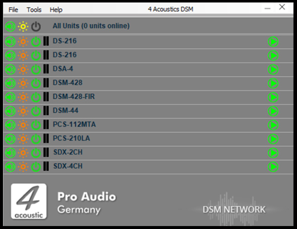
DSM Network Client
A single software solution for all devices. The DSM Network Client automatically scans the connected network and lists the DSM devices it finds. These may include SDX power amplifiers, active speakers, active line array speakers or DSM 19´´ devices. With just one click, you can open the configuration menu for the corresponding device. You can also group devices in the Network Client, allowing you to apply configuration changes quickly and reliably across the entire group.

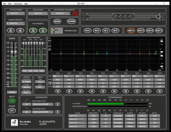
DSM Navigation Menu
To minimise the need to switch between different sections of the software, the navigation menu is located above all panels. The active preset display is on the left and may also include settings that were adjusted during operation. These settings are automatically saved in the active preset and remain available even after a restart. To save the active preset as a fixed preset on the device, assign a name, select the preset number and press the down arrow under 'Device Presets' to save it to the device memory. To load a preset from the device, select the preset number and press the up arrow. Please note that the active preset will be overwritten if it has not yet been saved. To save a preset to the computer, use the 'File Preset' function. The name displayed on the device and the network client can be customised under 'Device Name'. Use the menu buttons to navigate to the relevant configuration panels.
DSM Main Panel
The main panel provides an overview of all the input and output channels, and is fitted with gain controls and level meters. Each channel has a mute button. When operating in stereo mode, inputs A+B and C+D, as well as outputs 1+2, 3+4, 5+6 and 7+8, can be linked. The four input channels feature an input matrix that allows the physical input jacks to be routed to the inputs. In the lower fields, all inputs and outputs can be labelled as required to facilitate the assignment of functions within the system.
DSM Input Panel
The input panel is a high-quality tool for processing input signals within the DSM. Starting from the left, there is a gain control with a level meter and a mute button. To the right of that are the limiter and delay inputs, as well as the crossover settings for high- and low-pass filters. In the centre is the 10-band equaliser and filter unit. Each input also features a 4-band compressor-limiter located at the bottom of the EQ unit.
DSM Output Panel
The output panel is almost identical to the input panel. In addition to the output matrix, which allows any input to be routed to the output, it features a button for 180° phase reversal located below the Mute button. For FIR devices, FIR filter files for the corresponding output can be loaded via a menu accessible by clicking on the window displaying the graphs.
DSM Xover Panel
The Xover panel was originally designed to provide a quick overview of the high-pass and low-pass filter settings. Since then, it has evolved into a multifunctional panel that enables users to monitor and adjust a wide range of settings.
Product Overview
Power Amplifiers and DSPs